
Putting It All Together
A yacht description often begins with a compact row of names and dimensions. Those details become useful when they start explaining one another. A deeper keel affects access as well as the underwater arrangement. A larger sail changes the work at its sheets, its support and the hull beneath it. A button beside the helm belongs to a route through machinery, energy and a loaded component.
Take one boat all the way through those connections. The following yacht is hypothetical: its specification gives us a consistent arrangement to examine, rather than measurements or performance claims borrowed from a real builder.
Begin with the boat and its purpose
The design brief calls for coastal cruising by a small crew, with occasional club racing. It gives priority to manageable sail changes, access to the chosen harbours and equipment which the crew can inspect and maintain. Racing speed matters, but it must share the decision with those other uses.
The yacht has one hull, 11.8 metres overall and 10.6 metres on its stated loaded waterline, with a maximum beam of 3.6 metres. Its fixed fin keel carries lead ballast; a separate spade rudder turns on a stock worked by a tiller. Draught is 1.9 metres. Displacement mass is 6,800 kilograms in the departure condition, including crew, stores and liquids. Keep that loading state in view as we consider changes: it is the starting point for the boat’s immersion and weight distribution.
The hull is a glass-fibre composite shell joined to a deck with a foam core between its skins. Internal floors and bulkheads connect loaded regions. The keel bolts connect the keel to reinforced structure at the bottom of the hull.
A deck-stepped aluminium mast stands over a compression post; shrouds run over spreaders to chainplates supported by the hull structure. The forestay meets the mast below its head, and a backstay runs to the stern. A triangular mainsail is attached along the mast and controlled by a boom. A working jib occupies the forestay ahead of it, with sail and furling gear designed for roller reefing as well as complete stowage.
That arrangement is a fractional Bermudian sloop. Fractional locates the forestay below the masthead; Bermudian identifies the main’s triangular support arrangement; sloop identifies the ordinary main-and-headsail allocation on one mast. The aluminium spar and its standing rigging tell us how this particular version is made and supported.
The carried sail inventory consists of that mainsail and working jib, an asymmetric spinnaker for suitable freer courses, a storm jib for a removable inner stay, and a storm trysail with its own mast track and quarter-led sheets. The mainsail has two slab-reef positions, each with a reinforced tack eye for the reefing hook and a separate line controlling the new clew. The spinnaker’s tack can be carried on a retractable bowsprit. These are five carried sails from which the crew selects a working combination. The removable inner stay supports the storm alternative to the ordinary sloop plan.
The jib sheets lead through fairleads to manual self-tailing winches. The main halyard has an electric free-tail winch with a specified handle connection which disengages its powered drive for manual operation. A tiller pilot supplies heading control through a removable pushrod. A battery supplies their electrical energy. These last details identify particular available functions without promising that they can operate through every failure.
The cockpit has drains and a raised companionway threshold with closing boards and a sliding hatch. An anchor roller, rode, windlass and separate strong securing point occupy the bow. Mooring cleats have reinforced mountings and fair leads clear of sharp deck edges. The specification now contains a boat which must meet the shore and keep water outside as well as sail between places.
Follow one pull through the whole boat
With main and jib drawing on a reach, air pressure acts across their curved surfaces. The mainsail’s cloth carries tension towards its reinforced edges and corners. At the head, the halyard supports the headboard through its attachment; at the tack and clew, fittings transfer pull into the boom and adjoining controls. Along the luff, retained slides pass transverse load to the mast while permitting hoisting travel. The sheet acts through its blocks on the boom and the deck attachment. None of those named fittings can fulfil its job without the material beyond it.
The mast carries compression and bending. Shrouds and stays supply tension through their terminals and chainplates. Under the mast foot, the post takes compression to supporting structure below; around a chainplate, the connected hull structure distributes its pull. The keel connection, floors, shell and deck participate in the resulting loads. A stronger rope alone does not strengthen a weak chainplate attachment or a damaged core beneath a fitting.
Water acts on the moving hull, keel and rudder. The keel contributes side force as the boat makes leeway; the rudder changes its contribution as the tiller turns it in the passing water. The separated air and water forces produce turning and heeling effects as well as useful forward motion. The boat’s weight and buoyancy provide a restoring tendency through their changing separation when it heels. The stated ballast and draught help explain the arrangement, but their numbers alone cannot supply that separation at every angle.
Reefing or twisting this main changes both its working outline and its pressure distribution. The planform lets us compare projected shapes; the actual centre of pressure locates the resultant air force in the chosen state. Predicting the changed turning moment therefore requires the new force distribution, as well as the reduced outline.
At anchor, the force route changes again. The rode’s pull passes through its lead to the boat’s securing point and structure, while the anchor’s contact with the seabed resists it. The windlass can move the rode; its presence does not make the windlass gearbox the intended final holding point. Alongside, the mooring lines restrain particular directions through their own leads and cleats, while fenders carry contact with the berth. Understanding the yacht includes identifying which connection is carrying the current load.
Extra stores would immerse this hull more deeply and reduce the height of its openings above water. Clear cockpit drains and a sound companionway closure would still address water arriving on deck, but their suitability depends on the resulting exposure and pressure. Loading and water exclusion meet at those actual boundaries.
Change the wind before changing the boat
Now let the wind strengthen while the crew continues to reach. The main’s greater load can increase heel and alter the balance at the tiller. Easing the traveller moves the sheet’s lower attachment, changing the boom’s angle while much of the leech restraint can remain. Easing the sheet permits another change in boom position and twist, depending on the vang and the other restraints. To spill wind in this example is to unload some of the sail through those physical changes.
If less working area is needed, the first slab reef transfers the main’s effective tack to its reinforced reef eye and establishes a new clew through the reefing line. The shortened working sail still needs its head, luff and new corners supported. Loose cloth below the reef is gathered; light reef ties do not become the principal tack and clew attachments. The main’s area, height and distribution have changed together, so the resulting heel and helm cannot be inferred from area reduction alone.
The jib’s furling gear offers a different movement: rotation of its forward support winds cloth around it. A smaller exposed shape must still have a useful supported form. If the conditions instead call for the separate storm jib, its inner stay, tack, halyard and sheets establish another force route. The trysail likewise uses its own attachments when replacing the ordinary main. Carrying a storm sail is only the beginning of the handling question; the crew needs the means and opportunity to put that actual arrangement into work.
Suppose the yacht then heads upwind. A brief movement closer to the apparent wind can reduce the sail’s effective angle and load while enough headway remains. That is feathering in this setting. Continuing so high that drive and useful progress deteriorate is pinching. The boat may point closer to the wind while making more leeway and less progress towards it. Footing accepts a freer heading in exchange for speed; whether the exchange helps depends on the actual track and conditions.
For a separate illustrative comparison, suppose the yacht makes 6 knots through the water along a track 45 degrees from the water-relative true-wind direction. Its windward velocity made good, or VMG, is about 4.24 knots. Another state gives 5 knots along a track 40 degrees from that direction, producing about 3.83 knots of windward VMG. In those stated states, the less close track advances faster towards the wind. These are invented track-and-speed pairs, not a prediction that our specification can achieve either one. Using heading angles instead would require accounting for leeway; progress towards a destination over the ground would also require current and the destination’s direction.
A polar diagram for this yacht could put those alternatives beside others at the same wind strength. Its sail set and loading must match the comparison, and its angular and speed references must be stated. The inventory then identifies which surface supplies each plotted state. Pointing ability earns its value through the progress the boat actually makes.
Give changing states their proper names
On the next tack, the bow is meant to pass through the wind and the jib to transfer to its new working side. If the turn fails to complete, the yacht has missed stays. If it loses nearly all headway with the bow too close for normal sail drive, it may be in irons. The failed manoeuvre and the low-speed state are different parts of the account. As the normal forward water flow diminishes, the rudder loses much of its familiar response; a moving tiller alone does not prove a completed turn.
Holding the jib on the weather side can put air pressure on its normally opposite face. The jib is then aback, and its changed force can help turn the bow away or oppose forward motion, according to the current geometry. A loose sail snapping repeatedly is instead flogging: its folds and attachments receive repeated changing loads. Neither state should be confused with the smaller patch of disturbed airflow which can push in the mainsail’s leading region behind a headsail. Sailors can call that local interaction backwind. The sail, region and action identify what the word means here.
The same boat can deliberately retain a backed jib while the main and rudder contribute opposing tendencies, producing a slow hove-to state. It may gain a little headway, turn towards the wind, slow, and fall away again as those forces change. Continued slow headway is fore-reaching; it can coexist with the description hove to. Neither word promises a fixed geographical position. Our hull and rig specification does not establish the exact sail settings or motion which would work in a particular sea.
Take the working sails down altogether and the boat is lying ahull. Wind on the hull and bare rig, waves and water resistance now determine its drift and attitude without those opposing working-sail forces. That is a different physical situation even if an observer reports similarly little headway. The useful description tells us what is still acting, not merely that the boat has slowed.
On a later downwind leg, place the boom to port. If the apparent wind comes across the port quarter while the boom remains there, the boat is sailing by the lee. A wind shift or yaw can then change which face of the main is loaded and lead to an unintended boom crossing: an accidental gybe. The geometry exists before the crossing occurs.
For this changed condition, specify a preventer led from an appropriate boom attachment forwards through a supported lead and back to a controlled securing point. Its tension opposes the boom’s movement towards the centreline and transfers reactions to both boom and hull attachments. It does not prevent the entire yacht from yawing or remove pressure on a backed main. A boom brake, if fitted instead as the chosen arrangement, uses friction to moderate movement; it is a different restraint from securing the boom on one side.
A controlled gybe coordinates the intended turn with the main’s transfer, managing the sheet and other restraints so the boom crosses under control and the sail is set for the new side. That changes both heading and the position of a loaded spar. The specification and force explanation establish the jobs; they do not supply a universal operating sequence for every preventer, brake, sea state and crew.
If a wave or gust causes the yacht to turn up towards the wind, it rounds up. That direction of turn may be wanted or unwanted. A broach adds loss of directional control: the available steering action no longer contains the changed turning effects. Heel, sail force, immersed rudder geometry and water flow can all participate. Calling every round-up a broach would lose the distinction between a controlled heading change and a boat no longer answering as intended.
Change a feature and follow the consequences
Return to the original design brief and propose a lifting keel in place of the fixed fin. Reduced draught could open a shallower approach, but the change also needs a trunk or receiving space, guides or bearings, a lifting route and a way to retain the moving mass. The raised ballast occupies another position; its stability contribution changes. Raising the keel alone might leave the rudder as the deepest fixed part. Access is a whole underwater arrangement, not a number altered independently on a specification sheet.
A larger asymmetric spinnaker raises another connected question. Its extra cloth needs suitable tack and halyard support, a useful sheet lead and a means of setting, gathering and stowing it. The extended bowsprit and its supporting structure take the tack’s load. The existing boat’s dimensions cannot establish that those connections can accept the proposed sail. Racing use may favour the extra available area, while the cruising crew may place more value on handling fewer pieces of cloth through a change in conditions. That is cruising versus racing optimisation within two stated uses, rather than a verdict that one category always needs the larger rig.
Replacing the aluminium mast with a carbon-fibre composite spar could alter mass aloft and bending response. The proposal must specify the new spar’s structure, stiffness, fittings and supported sail shape. A lighter upper structure changes the weight distribution; it also needs its own reliable chain of manufacture, inspection and repair. The material name alone does not establish either its useful deflection or its remaining strength after an impact.
The MCA’s 2011 study of carbon spars describes how a small surface impact can accompany more extensive internal damage. For our proposed replacement, access to vulnerable attachments and a suitable inspection method belong in the design decision alongside reduced mass aloft. MCA, examination of carbon-fibre masts and spars, sections 3–4 and Appendix A.
Durability, repairability and recyclability ask different questions of that proposed material. Retaining strength in service, restoring a damaged connection and recovering constituents at the end of use are separate achievements. Clean production offcuts and a retired hull containing paint, core, fittings and repairs are different objects for a recovery process. The material’s origin or a successful scrap-recovery demonstration cannot by itself settle the assembled yacht’s service life or whole environmental effect. Those consequences belong beside the proposed structural gain when considering the design trade-off.
Keep control when assistance stops
If the electric halyard winch loses its supply, the specified manual override disengages the powered drive and permits handle input. The crew must now provide the work, retrieve the line and manage the sail, potentially at a slower rate. That alternative addresses the failed supply. A jammed drum or fouled halyard would still block the shared route.
Now add a specified controller which stops this winch’s motor when its configured current threshold is exceeded. Its overload protection interrupts drive input. The sail can remain raised, the halyard stretched and the fittings loaded after the cutoff, retaining stored energy. The crew still needs to establish why demand rose and which movement remains available. This boat’s specified stores are its battery, elastic extension and raised masses.
The tiller pilot’s removable pushrod supplies another useful handover: disconnecting it leaves the crew able to work the tiller if stock and rudder remain usable. A second control panel sharing the same failed drive would preserve no extra steering movement. An auxiliary rudder would add another blade and shaft, but that would be a further alteration to our specification. Redundancy is useful only through the particular function and failure it addresses.
The battery stores energy supplied earlier. Wind can continue providing propulsion while the electrical store supplies intermittent sail adjustment and sustained steering work. A full day under sail therefore does not tell us the remaining battery charge, just as a fitted motor does not tell us whether a loaded line can be released after a particular failure. The sail-driving flow, control demand, source and store have separate roles in the same voyage.
Read real boats with the same questions
Other briefs combine familiar components differently. Dorade, designed in 1929 and launched in 1930, provides a classic comparison. Its documented ocean-racing arrangement combined a narrow hull, deep lead ballast, a Bermudian yawl rig and steam-bent framing. Its historical account identifies Six-Metre influence and contrasts its bent frames with sawn construction. Those particulars connect a racing purpose, available skills and a structural choice; the date alone would tell us none of that. Dorade’s documented history.
Compared with our sloop, the smaller after mizzen divides sail area and introduces another force farther aft, with its own support and controls. That is a concrete change to investigate alongside Dorade’s documented hull and ballast choices. Its restored present configuration must be distinguished from the known 1930 arrangement when making the comparison.
Path makes the access and handling comparison at a much larger scale. Baltic’s delivered 2021 yacht is a 44.60-metre sloop with a lifting keel, twin rudders and captive winches. The builder lists three furled upwind sails and additional sails carried from a removable bowsprit. Those are separate sailing choices supported by substantial handling machinery. Its published draught changes between 5.9 and 3.4 metres. Baltic’s Path project record.
The builder’s October 2021 account connects the keel and twin rudders to shallow access and reaching control, within a family cruising brief that values manageable, maintainable systems. It also describes the storm staysail and reduced main as an intended combination. These are useful documented purposes. They do not disclose every keel lock, valve or emergency-release connection, nor establish the same behaviour for our proposed smaller lifting-keel yacht. Baltic’s dated design account.
Path’s builder table labels its mass figure light displacement; our sloop’s departure figure includes people and stores. A mass comparison needs equivalent loading states. Tonnage versus displacement raises a different distinction again: an assessed volume under a tonnage convention cannot replace either yacht’s mass in the stability calculation.
Malizia–Seaexplorer’s July 2022 launch gives an advanced racing comparison. Its VPLP design and Multiplast construction combined curved hull lines, a spoon bow, foils and a reorganised working space. The launch account tied those choices to sustaining high average speed in rough water, with both solo and crewed racing intended. That is the stated design aim at a dated launch, not a controlled measurement of each feature’s benefit. IMOCA, 19 July 2022 launch account.
The foils bring additional water force into that moving hull through their supports. Any upward contribution changes the share carried by buoyancy, while the working-space arrangement affects how the crew can sustain adjustments in rough water. The launch account states the aims; measured performance and later revisions require their own evidence.
Change the complete sail allocation
Sea Cloud’s published sail plan makes a much larger change to sail allocation: square stacks on the first three of four masts, then a gaff sail and gaff topsail on the last. It is a four-masted barque, with fore-and-aft headsails and staysails supplementing the square stacks. The plan names the positions fore, main, mizzen and spanker, and places a skysail above the mainmast’s royal. Sea Cloud’s published sail plan.
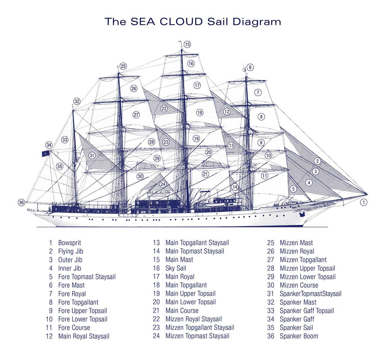
Compared with our sloop’s sheet-controlled boom, this rig allocates turning, corner restraint and gathering among braces, sheets, clewlines and buntlines. The after gaff sail retains its different throat, peak and mast-side supports. A sail plan establishes that broad organisation; deck leads and hidden fittings need further drawings. The operator’s history also records rig changes after the yacht’s 1931 beginning, so the present plan belongs to a later configuration. Operator’s history.
That allocation changes the room and work needed to turn. Wearing ship takes the conventional square rig away through the downwind route while crew coordinate the yards and sail forces. Its excursion to leeward matters beside a constrained shore. Our sloop’s tack instead sends its permanent bow across the wind.
The earlier canoe’s shunting changes which end leads while keeping the outrigger to windward. Transferring that manoeuvre to our boat would require changing the relationship between hull ends and rig, not simply choosing another tiller movement. Names for manoeuvres carry whole-boat assumptions.
These arrangements continue to serve different purposes. Even the superficially similar transverse sails of a conventional barque and DynaRig lead to different working questions: can the yard turn around a fixed mast, or does the supported mast rotate with the sails? Where does the cloth go when gathered? The permitted movements turn an outline into an intelligible boat.
Ask what a comparison has actually established
Return to the proposed lifting keel and larger spinnaker for our cruising sloop. A scale model in a tow-tank test could compare the underwater shapes’ resistance under declared conditions. A wind-tunnel test could compare rig forces at selected settings; computational fluid dynamics, or CFD, could calculate flow for specified geometry and assumptions. Each addresses a part of the proposed change, with the scale, deformation and fluid-model limits established earlier.
A velocity prediction program, or VPP, would bring the modelled air and water forces together to predict sailing states. Its polar could test whether the proposed change is expected to help in the chosen wind and loading conditions. Sea trials would then supply observations from the actual boat. A disagreement is useful: it sends us back to the assumed shape, trim, loads and measurements which produced the prediction.
For a historical boat, an experimental reconstruction answers another part of the problem: whether a particular interpretation of the surviving arrangement can work. A trial tests the new vessel actually built. Connecting that result to the original requires the historical evidence, just as Dorade’s restored configuration and its documented design history must be kept distinct.
Club rules may settle whether either proposed change is eligible. A one-design restricts variations; a development class makes defined design freedom part of the contest; a rating rule can change the allowance assigned to a modified yacht. A larger spinnaker could therefore improve the boat’s predicted speed yet change its racing terms. Corrected results answer the rule’s comparison rather than isolating the sail’s efficiency.
The design brief therefore remains necessary at the end of the comparison. Greater predicted speed may be useful, but the chosen harbour could still be too shallow, the sail change too demanding for the intended crew, or the new structure difficult to inspect. A good explanation connects the gain to the rest of this boat. It also identifies which facts were supplied, which consequences follow under stated conditions and which still require drawings, records, tests or observation.
Return to carrying, movement and control
The first boat gave people somewhere to be carried. Its maker could hollow timber, bind floating material or cover a framework according to the resources and skills available. A paddle, pole or oar then connected a person’s work to the surroundings. The rowlock’s bearing and retaining parts mattered because the useful force needed somewhere to pass into the hull.
A sailing yacht makes that connection through many more parts. Air acts on supported cloth; water acts on hull and underwater surfaces. Weight, buoyancy and separated force lines determine how the boat sits and tends to turn. Ropes, spars, fittings and structure carry loads while controls permit selected movements. Machinery can supply work and sustain adjustments, but it still needs those physical routes and people who understand the remaining choices.
Technical history follows changes within those arrangements: what was made differently, which work it enabled, and which materials, skills or experience made it useful. Dates locate the evidence. Dorade’s documented framing and sail choices, Path’s access and handling brief, and Malizia–Seaexplorer’s rough-water design aims do not form a universal ranking. Nor does the order in which we learned to explain a square sail, a triangular sail or a foil establish their historical descent.
The names make that understanding portable. A headboard locates a load entry; a shroud identifies a supporting tension member; a preventer identifies a particular restraint. A barque, a fractional sloop and a shunting canoe describe arrangements with different working relationships. When an unfamiliar yacht is described, those words let us begin tracing what supports it, what moves it, what restrains it and what its people can change. The boat is still carrying a load through water. Its particular way of turning moving air into a chosen journey is what we have learned to read.